Over the past 45 years of helping precipitator owners/operators in North America, we have run across quite a few recovery boiler precipitators. The support we have provided tend to be in response to one or more of these common issues;
- Poor kV input
- Ineffective rapping
- Gas flow issues
Three processes are necessary for a properly functioning precipitator:
- Charging; the process that creates the ions which charge the dust particle
- Collecting; the process by which the charged dust particles migrate to the collection surfaces
- Removal; the process that involves rapping off the collected dust particles and removing them from the precipitator
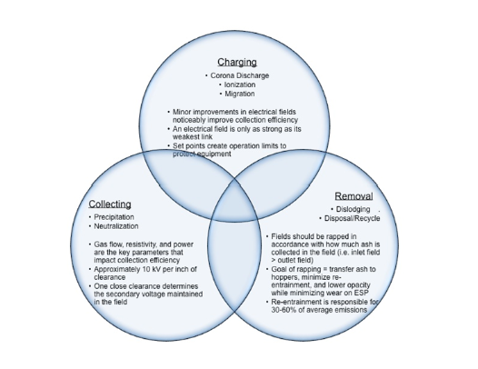
Precipitators are not so forgiving. If one of these steps is not performing optimally, overall precipitator collection performance degrades. You cannot get away with just 2 steps working well.
Diagnosing issues with these steps can be difficult because a symptom may be the result of one or multiple issues within each of the steps that collectively contribute to poor performance.
Let’s break down the performance issues listed above and look at some of the most common causes of each.
Poor KV Input
Maximize secondary voltage (kV) input and you maximize precipitator collection efficiency. Simply put, kV is King! Here are the major culprits to not being able to maximize kV input.
You’re only as good as your closest clearance.
Misalignment between collecting electrodes and discharge electrodes (i.e wires, RDEs, etc) results in reducing the point at which the field wants to spark or what is referred to as spark over voltage. This results in lower kV input, along with lower secondary current (mA) input and lower overall power input (kW). Thus, maintaining good clearances is essential for efficient precipitator operation. Remember, every one (1) inch of clearance between a plate and discharge electrode equates to 10kV. That means that close clearances degrade the available power input into the field by 10kV per inch of clearance lost. Also, depending on your plate spacing and discharge electrode geometry, current does not begin to flow until 18kV-20kV. Why is kV so important? Keep reading.
Alignment of the upper discharge electrode frames and the lower anti sway frames is critical. Removing or repairing bent/warped plates is important, however it may be easier to just remove the wire/discharge electrode(s) that is being affected.
Check your controls
In order to get the best performance out of your precipitator, the voltage controller must be allowed to operate as close to the spark-over voltage as possible. Most controllers used today are modern, microprocessor-based controls. They are not fool proof. They depend on good feedback from the Transformer/Rectifier sets to operate properly. Issues seen that prevent these controls from optimizing performance are:
- Control limit settings programmed lower than the T/R set nameplate
- Calibration of the input signals is out of spec.
- Too low a spark rate set on the controller.
Solutions range from confirming controller set up matches T/R set nameplate rating, periodic checking of feedback signal calibration (yes, even on those “non calibration necessary” controls) and checking spark rate settings.
Corona Quenching
A Corona beer will quench your thirst, but that’s not what we are talking about here. This is also referred to as Space Charge Effect.
Very fine particles are formed in the recovery boiler and there are a lot of them. This large number of very small particles has a shielding effect on the power input once they arrive at the precipitator. These particles, because they are lighter than the larger particles, partially migrate to the collecting plates and stay entrained in the gas stream. While they are floating around, they repel other similarly charged particles (same polarity). This condition is prevalent in the inlet fields of a precipitator where the dust loading is the highest.
This condition requires more kV gain for more efficient operation. Solutions range from making sure the controls are not set below nameplate ratings (easy) to better matching T/R set output to the field (harder).
Ineffective Rapping
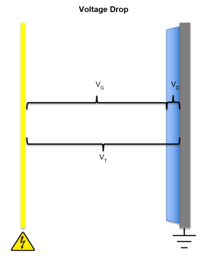
What keeps the dust on the plates until you are ready to remove it? Answer: Clamping force. Clamping force is the voltage drop across the dust layer on the plates.
The key to optimal rapping is to build up enough mass on the collecting plates, allow the clamping force to keep it there, and then apply a mechanical force that breaks the electrical bond to drop the dust into a hopper.
Salt cake (dust) is relatively low resistivity (ohm/cm), thus it is easy to charge and collect. But, it’s also easy to remove, even when you don’t want to. This is because the voltage drop, and clamping force, are low. This results in the dust easily re-entrained back into the gas stream either by disturbances (gas velocity, sparking) or rapping.
To make matters more complicated, Salt Cake can be adhesive. The chemistry of the dust and combustion conditions can create a sticky dust that becomes crusty and difficult to remove.
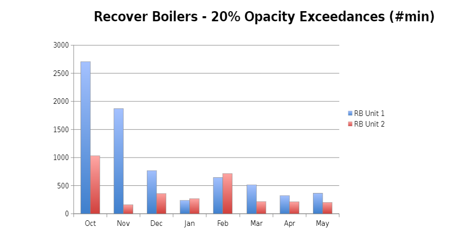
Both present challenges to rapping. Too aggressive rapping (repeat cycles, impact force) can cause the dust to be re-entrained, which leads to high emissions. Rapping too infrequent, and build up occurs, potentially allowing crusting and/or too large amount of dust falling off the plates causing a massive disturbance in the precipitator and emissions spikes with rapping. Both conditions cause the typical “opacity spiking” problem users experience.
Since rapping is more “art” than “science”, the solutions require time and patience. Most of the solutions revolve around assessing the rapping programs (repeat times, impact) and trial and error of changes to find the optimal program. For example, Inlet field rapping repeat times may be every 4 minutes while the outlet field may only rap once a day.
Gas Flow Issues
One of the most ignored problems that can have the most impact on the precipitator is with gas flow.
A hole lot of air
The sizing of your precipitator, including height and width of the fields, the number of fields and the number of collecting plates, was determined with a specific gas volume in mind. Any “extra” that was not planned for negatively impacts performance.
The ingress of air from holes in the duct work, expansion joints, or casing will increase the amount of volume to the precipitator, actually making ithe precipitator “smaller”. This will increase emissions. Another issue that results from air ingress is corrosion of precipitator internals that lead to close clearances and failed components, problems mentioned earlier.
The solution is to patch the holes and replace the seals. This could be the least expensive solution you perform to improve performance.
Sneaky Gas
Once it gets into the precipitator, the gas may not go where you want it to go. The design of the flow control devices in the duct work, the design of the precipitator inlet nozzle and/or dust build up on gas flow devices can force the gas to “sneak” under the collection zones and exit the precipitator without being treated.
Baffling is installed between the end walls and plates, and in the scraper area or hoppers (depending on wet or dry bottom) to prevent gas from sneaking through these areas. Maintenance on these devices is important. If these have been removed, put them back in place!
Uniformity
Gas velocity profiles should be as uniform as possible across the precipitator height and width. Areas in the precipitator that see more gas flow will see more dust loading. The high dust loading can create a space charge effect that results in poor performance.
High concentration of gas velocity towards the bottom of the precipitator does the same as the above with the addition of expounding the impact of the lack of baffles.
Uniformity can be influenced by the adhesive nature of the dust. Plugged perforated plates and dust sticking to horizontal flow devices can cause temporary uniformity issues. Sometimes, these devices must be redesigned if the buildup is reoccurring.
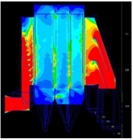
Existing gas flow velocity patterns can be confirmed by performing a dirty inspection (dust concentration) or performing a flow model study. Solution development and testing is performed using a flow model study.
Don’t assume the flow control devices that were installed in 1985 are optimal for today. Any change in process (i.e throughput, soot blowing rates, firing rates, temperatures, etc) change the characteristics of your gas stream. And, the performance expectations have gotten more stringent over time, so you aren’t likely chasing the same collection efficiency as it was designed to meet. Our experience with improving uniformity in gas flow has resulted in 50% plus reduction in emissions. It’s an easy and relatively inexpensive improvement to gain performance and operational flexibility.
Conclusion
Poor kV input, ineffective rapping, and gas flow issues are some of the most common problems with recovery boiler precipitators that result in opacity exceedances and production curtailment. Multiple variables influence precipitator performance, including those from combustion, flue gas and salt cake chemistry, and precipitator equipment. Understanding how all these variables interact is important in our efforts to optimize performance (i.e. more emissions margin, higher recycle rates) or troubleshoot issues (high opacity, poor reliability).
Three things we need to remember relating to precipitator performance are; 1) kV is king, 2) you’re only good as your closest clearance and 3) 10kV per inch of clearance between the discharge electrode and plate. With these in mind, we can begin to ask the right questions.